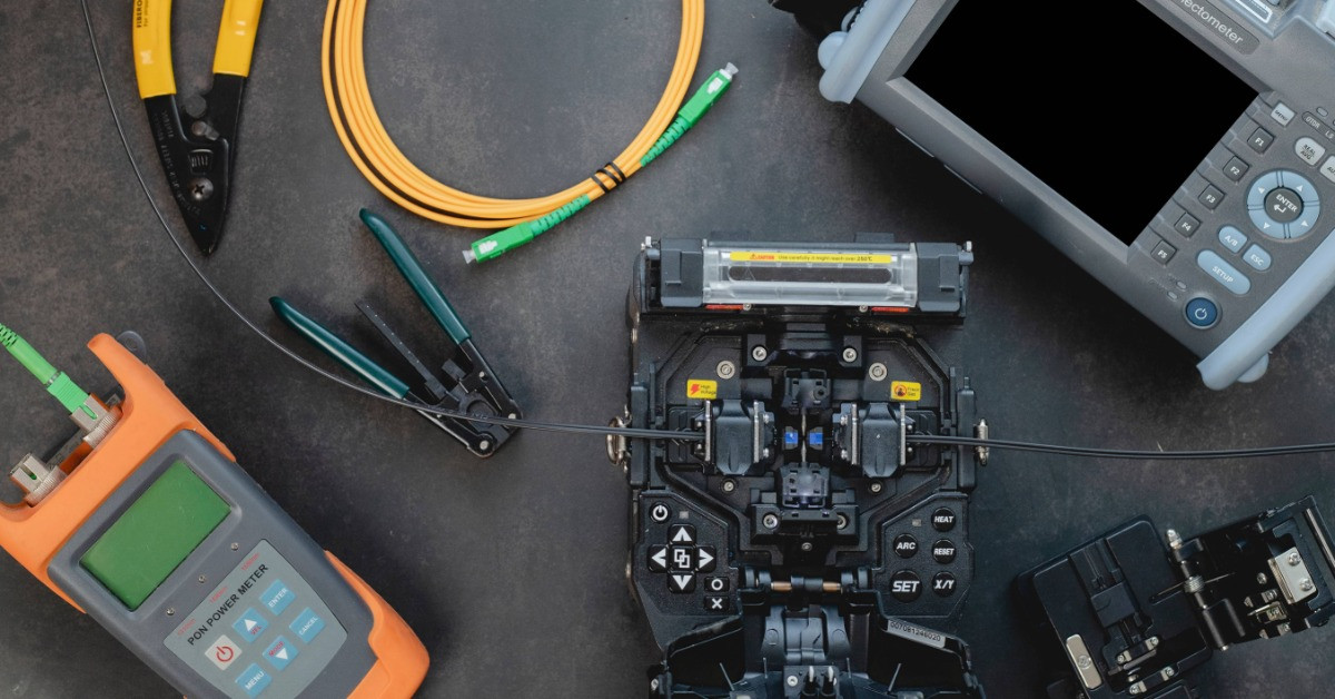
Integrating an OTDR into a fixed splicing trailer bench means positioning it at the test-station end after the fusion splicer. This location accounts for mounting a permanent launch-cable spool at its port, feeding it a dedicated surge-protected 15A circuit, and routing the fiber through labeled pass-through doors for clean bidirectional testing.
The OTDR (optical time domain reflectometer) is the primary quality-verification instrument on a fiber optic splicing trailer, and its placement, power, and launch-cable storage must be engineered into the bench before the unit leaves an area. Millennium Broadband Solutions created this guide for crews building or speccing a trailer for rural broadband work.
What Is a Fiber Optic Splicing Trailer?
A fiber optic splicing trailer is a climate-controlled mobile workstation that lets crews strip, cleave, fusion-splice, and test fiber on site without hauling cable to a lab.
The core payload sits on a fixed bench with the following features:
- Fusion splicer and precision cleaver
- OTDR, optical power meter, and visual fault locator
- Fiber reels and slack storage
Support systems make the bench usable in the field, such as:
- HVAC for temperature and humidity control
- Generator or shore power
- Interior task lighting
- Gasketed cable-access doors
- LTE, 5G, or satellite internet connectivity for trace uploads
Rural crews depend on these units to keep builds on schedule. Millennium’s equipment and reel trailers supply the placing and transport side of rural builds.

Where the OTDR Sits on the Splicing Trailer Bench
Contractors should mount the OTDR at the test-station end of the bench, which is downstream of the fusion splicer so that the layout enforces a strip, cleave, splice, test sequence with no backtracking.
The following placement rules protect accuracy and the instrument:
- Keep the display situated at eye level with ports facing the technician to reduce handling errors on live fiber.
- Store the unit in a padded, secured mount—never loose on a shelf—so that it survives transit and maintains calibration.
An OTDR Launch Cable: Why the Trailer Needs One
A launch cable is a 500 m to 2 km single-mode spool, also called a dead-zone eliminator, that absorbs the OTDR’s near-end dead zone. This allows contractors to measure the first real splice.
Without the launch cable, the dead zone masks the first splice and corrupts the loss reading. Build the spool into the bench as follows:
- Mount the launch box in a fixed, labeled position adjacent to the OTDR port, not as loose gear that walks off between jobs.
- Use pre-connectorized launch and receive spools so that crews can easily plug in and test without re-terminating each shift.
- Add a receive spool at the far end to expose the last splice the same way as the first.
Running Bidirectional OTDR Tests From the Trailer on a Long Rural Span
Run traces from both fiber ends and average them per ANSI/TIA/EIA-455-8 to cancel backscatter artifacts that produce false gainers.
A single-direction trace can report a splice as a gain because the two fibers backscatter light differently. Averaging both directions returns the true loss. Keep the following steps in mind for improved accuracy in bidirectional testing:
- Install labeled cable hooks and reels so that the test cable runs toward the access door and back cleanly.
- Coordinate the far-end test with the crew at the opposite splice point.
- Capture a trace from each direction, then average the two readings per splice.
- Keep a launch cable at both ends so that dead zones fall outside the measured span.
Power Supply and Circuit: What Does a Trailer OTDR Require?
Feed the OTDR from a dedicated 15A 120V AC circuit with surge protection, isolated from the HVAC compressor load on the same generator. Voltage sags from an HVAC startup or generator fluctuation can interrupt a trace mid-capture or corrupt a stored .sor file. Support the trailer OTDR with the following tips:
- Keep the OTDR on its own circuit, apart from the fusion splicer, so neither instrument’s inrush current disturbs the other.
- Add surge protection between the generator and the test instruments.
- Choose battery-backed handheld OTDRs as a buffer against brief generator dropouts while parked on uneven ground.
How Vibration and Climate Control Affect OTDR Accuracy
Road shock damages OTDR optics and corrupts stored traces. Vibration on uneven ground injects false trace events. Torsion-axle suspension and anti-vibration bench surfaces can prevent both issues.
Temperature swings beyond ±10 degrees Celsius shift the OTDR’s dynamic range and backscatter calibration, making a properly sized HVAC system a test prerequisite, not a comfort feature. Contractors should consider the following:
- A stable interior keeps fusion-splice arc output consistent.
- Controlled humidity keeps cleaved end faces clean.
- Store the OTDR in its padded mount during transit and power it up only after the interior stabilizes.

Splice-Loss Thresholds and Wavelengths
Generally, contractors can accept a fusion splice only when average loss stays under 0.1 dB and no single splice exceeds 0.3 dB at 1310 nm, measured bidirectionally and averaged.
Common parameters and targets are as follows:
- Average splice loss: Under 0.1 dB
- Maximum single splice: 0.3 dB at 1310 nm
- Test wavelengths: 1310 nm and 1550 nm
- Minimum dynamic range: 36 dB for 20–80 km spans
- Test method: Bidirectional, averaged per ANSI/TIA/EIA-455-8
Test single-mode fiber at both wavelengths. The 1550 nm trace exposes the macrobend loss that 1310 nm testing hides. Spec at least 36 dB of dynamic range for the long rural spans these fiber optic splicing trailers serve.
Routing Fiber and Close Out Documentation From the Bench
Bring live fiber through gasketed, labeled access doors specifically positioned so that the run reaches the bench port without bending below its measured radius. Plan a slack loop between the pass-through and the port so that technicians can dress the fiber and stage the launch cable cleanly.
Modern trailers close the documentation loop on site with the following features:
- Integrated LTE, 5G, or satellite internet uploads .sor file traces to a NOC or cloud platform, closing as-built packages without a drive back to the office.
- Handheld multifunction units combining OTDR, VFL, and OPM shrink the bench footprint compared to separate benchtop instruments.
Putting It All Together on the Splicing Trailer Bench
A fiber optic splicing trailer performs only as well as the workflow engineered into it. When the bench layout mirrors the strip, cleave, splice, test sequence, crews close out as-built packages faster and return fewer failing splices. Integrating OTDRs into fixed splicing trailer benches correctly at the start separates trailers that deliver on rural broadband timelines from those that don’t. Partner with Millennium Broadband Solutions for structured support with equipment, repairs, and field work.